![]() ၀-၉
၀-၉
In LinK – HM
HART Protocol Modem Module
with HART Device to Modbus Accumulator
for OEM Applications
ဆော့ဖ်ဝဲကို စနစ်ထည့်သွင်းပါ။
တပ်ဆင်ခြင်းနှင့် လုပ်ဆောင်ချက်လက်စွဲ
InLink-HM 101-0014 HART Protocol Modem Module

InLink-HM 101-0014 is a complete OEM HART® protocol modem module with managed HART host timing to function as either a primary or secondary HART host – eliminating the need for external CD monitoring and RTS control. It can also be used as a HART to Modbus accumulator polling up to 16 HART devices. For evaluation and development support, the InLink-HM module is compatible with the 101-0003 InLink evaluation board and pin-compatible with the InLink-TC module. The InLink-HM module is also compatible with the InLink-HM Evaluation Board RS-485 (part number 101-0093). Compatibility of the InLink-HM module with the InLink-HM evaluation board RS-485 requires Firmware version 6 or higher.
InLink-HM can be easily interfaced to most micro-controllers using only two I/O pins: transmit data (TXD) and receive data (RXD), typically connected to USART I/O. Unlike many HART modems, communications direction control is managed internally, so there is no need to handle tricky request-to-send (RTS) and carrier-detect (CD) handshake timing, greatly simplifying software development.
As a HART protocol modem, InLink-HM receives packets on the TXD input pin, at the configured baud rate and parity setting, and then sends the packet to the HART loop. After sending the packet, InLink-HM switches the modem to receive to acquire the reply. The reply is transmitted on the RXD output pin at the configured baud rate and parity setting. The DE output pin provides RS-485 half-duplex transceiver data direction control.
InLink-HM can be configured to continuously poll up to 16 HART devices and save the HART device data into Modbus registers. Modbus RTU commands can then be used to read the HART device data. Configuration is simple using the included HM Configuration software. Settings are saved in Modbus RTU registers, so Modbus RTU commands can also be used to edit the InLink settings. The InLink-HM module can be restored to default settings using the HM Configuration software.
620-0020 R4 Microflex 2016-2025
InLink-HM Block Diagram

လုပ်ဆောင်ချက်ဖော်ပြချက်
InLink-HM includes a complete HART protocol modem with transformer isolation and capacitor coupling to the HART loop. The two HART pins can be connected directly to the loop without concern for polarity. The HART loop resistor, typically 250 ohms, is not included but is required. The TXD, RXD, and DE I/O pins are compatible with 3.3-volt logic, and the module requires an external 3.3-volt power supply connected to VDD.
HART Modem Mode
InLink-HM ships are configured to function as a typical HART protocol modem and are compatible with most HART configuration and test software. Included on the CD are the PACTware FDT frame, HART Protocol DTM, and Microflex Generic DTM software. For information on installing PACTware and the DTM, please reference the PACTware Quick Start Guide. Also included is a HART device addressing utility, which can be used to configure the polling address in HART devices for multi-drop systems.
To function as a HART protocol modem, the module is typically configured for 1200 baud, odd parity, with modbus register filling disabled. When set to use higher baud rates, InLink-HM will receive the HART command at the higher baud rate and then transmit through the modem at 1200 baud odd parity. The HART reply packet is received by the InLink-HM modem and then transmitted back at the higher baud rate on the RXD output pin. HART packets must be formatted in the standard format and include the “FF” preamble characters. If InLink-HM receives “FF” (hex) as the first byte in a new packet, it is assumed to be a HART packet, and InLink will switch to the HART modem mode and stop filling Modbus registers if enabled. If no HART commands are received over the serial port after 30 seconds, InLink-HM will return to polling and filling modbus registers. Also, if a Modbus command is received, InLink will exit HART mode and return to polling and filling Modbus registers. Modbus packets begin with the slave address or universal address 0, but never FF (hex).
Fill Modbus Registers Mode
InLink-HM can be configured to continuously poll a HART loop of 1 to 16 HART devices and fill Modbus registers with HART device variable data – up to 4 variables per device. When enabled, the module will work through a list of HART device polling addresses and use HART command 3 to read the primary, secondary, tertiary, quaternary variables, as well as the loop current. Values are saved in 16-bit signed registers and single-precision floating point (two 16-bit registers per floating point value). The register values can then be read using Modbus command 3. Registers can be grouped by HART device or variable type.
ဖွဲ့စည်းမှု
The InLink-HM configuration is set using a few Modbus setup registers. Refer to the Setup Registers section in this manual for details. The configuration can also be changed using the Microflex HM Configuration program running on a Microsoft Windows PC. The InLink-HM module will need to be connected to a PC serial port to use the HM Configuration software. This can be done using the InLink evaluation board (part number 101-0003). Microflex also offers the InLink-HM Evaluation Board RS-485 (part number 101-0093). InLink-HM Evaluation Board RS-485 includes the necessary RS-485 half duplex transceivers to connect the InLink-HM module to an RS-485 network bus.
Power Supply – 3.3V / GND
InLink-HM requires an external 3.3 volt DC power supply (3.6 volts max). When using the InLink evaluation board, a 3.3-volt supply should be used. To prevent any noise interference to the HART modem, the power supply should be heavily filtered and decoupled to ground. Typical supply current is less than 5 mA. Wait at least 25 milliseconds after powering on before starting any communications transactions.
Serial Port – TXD / RXD
The InLink-HM serial port uses 3.3-volt CMOS logic levels. The InLink evaluation board (101-0003) provides the transceivers necessary to connect the module directly to an RS-232 serial port. The TXD and RXD lines will typically connect to microcontroller IO pins in your OEM application.
Driver Enable – DE
The Driver Enable pin is a Digital Output, Active High. A logic high indicates that a HART or Modbus reply packet is being shifted out serially on RXD. DE can be used for RS-485 transceiver direction control. Firmware version 6 or higher is required for Driver Enable (DE) functionality.
HART Loop – HART
These two pins connect to the HART loop. The internal modem includes transformer isolation, AC capacitor coupling, and line transient protection. The two pins are designed to connect directly to a HART protocol loop. Connections can be made across the HART 230 to 600 ohm loop resistor or across the HART device. All HART loops are required to have a loop resistor.
HART Device Polling Address
Each HART device has a polling address. By default, devices are set to use polling address 0 with the current output enabled. Before a HART master can send commands to a device, it must first use the polling address to learn the unique 5-byte device address. HART command 0 is sent with the polling address set to 0. The HART device replies with a packet that includes the necessary information to build the 5-byte-long address. With the long address learned, the HART master can then send any other HART command to the device.
For multi-drop loops where more than one HART device is in the same loop, each HART device must be set to have a unique polling address. For HART version 3 – 5, the polling address for multi-drop devices can be 1 to 15. For HART version 6 and higher devices, the polling address can be 1 to 63. In multi-drop mode, the current output is set to a fixed value and cannot be used for a process value.
Setting the HART Device Address
HART command 6 is used to set the device’s polling address. The HART host must first use command 0 to learn the long address. The device polling address should only be changed on a HART device that is not controlling or measuring a live process, since the change may alter the current output as well as interfere with a HART master’s ability to communicate with the device. The configuration software for your HART device should include the capability to set the device’s polling address. The Microflex HART Host app includes the capabilities to scan for and change a device’s HART address.
InLink-HM HART – Modbus Accumulator
In addition to being a HART Protocol Modem module, the InLink HM can be set to collect and store process variable information from up to 16 HART devices. HART devices are continuously polled, and variable information is accumulated into a table of Modbus registers. Using the InLink Evaluation Board serial port, the registers can be read using Modbus RTU command 3. Variable data can be read as 16-bit integers or 32-bit floating point. Up to 4 variables for each polled HART device.
In the accumulate mode, InLink-HM will function as a HART master (primary or secondary) polling devices and storing variable values into registers. No additional HART software is needed. The HART loop may contain a single device or up to 16 devices. When more than one device is in the loop, each HART device must have a unique HART polling address. The address for each device is set before wiring the device into the multi-drop loop. The device polling address for each device is stored in the InLink-HM using the HM Configuration Software.
Modbus slave address, baud rate, parity, and other settings are set using the HM Configuration Software. Configuration is done using the same port that Modbus will use, so no additional setup cable is required. After the configuration is completed, the port is connected to the Modbus controller. Upon powering on, the InLink-HM will begin polling and accumulating values. Modbus RTU command 3 is used to read the accumulated values.
HM Configuration Software Installation – Windows
The HM-Configurator software is used to configure the MicroLink-HM serial port and Modbus accumulator mode. All of the configuration settings are saved in Modbus registers and can also be set using Modbus RTU command 6 or 16. Details, including register definitions, are included in the Installation, Operation, and Specification manual. The MicroLink-HM can be connected directly to a Windows PC RS-232 serial port or a USB-to-serial converter cable.
တပ်ဆင်ခြင်း။
Download the HM-Configurator app from
https://microflx.com/products/hm-configuration-software-app

ဒေါင်းလုဒ်လုပ်ထားသောကို Run လိုက်ပါ။ file to install the HM-Configurator.
After Installation, the HM Configurator icon will be added to your system.
ပင်မစခရင်
The home screen displays a summary of the HM Configuration status, HART modem settings, and Modbus settings. Use the top drop-down menus to configure the InLink-HM modem.
Set up the COM Port
The HM Configuration software must be set to use the same COM port that the modem is connected to. From the top menu, select Setup>Com Port. Choose the COM port number from the list of available ports. After choosing, click Connect to attempt to connect using the settings selected. The connection process will first try the last good baud rate and parity settings. If it fails to connect, the process will work through other settings to try to find the correct InLink-HM settings for communications. If it still does not connect, verify that you have chosen the correct COM number, connections are correct, and power is on before trying again.

HART Protocol Settings
With Fill Modbus Registers unchecked, InLink-HM will function as a standard HART protocol modem and not poll HART devices to fill Modbus registers. In this mode, HART packets are received and then retransmitted at the HART 1200 baud, odd parity. Received reply packets are retransmitted at the selected baud rate. RTS timing and carrier detection are handled internally by the InLink-HM, allowing communications at higher than 1200 baud. HART loop data is handled at the standard HART protocol 1200 baud, odd parity, but because InLink-HM buffers the data, the port can be set for higher rates as well as odd, even, or no parity. Port settings can be set in the Modbus Settings section.
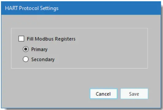
Since InLink-HM manages network timing, it needs to be configured for either a primary or secondary master. Configuration modems are typically set to be secondary masters.
Polling HART Devices – Fill Modbus Registers
To enable Modbus register accumulation, check the Fill Modbus Registers option. The Hart Protocol Settings window will expand to show the Polled Devices settings.
ပြန်စမ်းပါ။
If a HART device is polled but does not respond, or errors are detected, InLink-HM can retry up to 3 times before indicating a bad device. If a device is not responding, the Modbus values are filled with Hart Device Failed register values – setup is done in the Modbus configuration section.
Polled Devices
ဟောင်း၌ample screenshot (Figure 5), InLink-HM is set to poll one HART device using polling address 0 and will retry 1 time before reporting a communications error. The Device Variables (Modbus Register Values) box on the right displays the register values for the active polled device. Click Add Device to add a polled HART device. Be sure to set the Polling Address for each device. Each device must have a unique HART polling address. Polling addresses must be set up for each HART device before it can be connected to a multi-drop HART loop, and can be set from 1 to 63.
Address O can only be used when one device is in the HART loop.
Polling addresses 16-63 should only be used with HART revisions 6 and higher. For HART 3-5, use addresses 1-15 for multi-drop systems.
 Figure 5. HART protocol settings dialog when filling Modbus registers is enabled.
ဒဿမနေရာများ
When device data is stored in a 16-bit signed Modbus register, the value can range from -32768 to 32767. To allow the 16-bit integer to represent a smaller number and include fractional information, the number of decimal places is stored in a separate Modbus register and applied later. The number of decimal places can be set from 0 to 5. Decimal places can be set for each variable. The Device Variables box shows the effect of the decimal place setting. Decimal place settings are not used for the Modus floating point register values.
Modbus – RTU Setup
Modbus-RTU Settings can be accessed and changed by clicking Setup>Modbus from the top drop-down menu.
 Figure 6. Modbus settings dialog.
Modbus လိပ်စာ
Each device on a Modbus network must have a unique address. Set this to match the address that your Modbus master will use to communicate with the InLink-HM. The Modbus address can be set to any value from 1 to 247. The HM Configuration software will discover this address as part of the connection process.
Baud Rate & Parity
The InLink-HM baud rate and parity must be set to the same settings as your Modbus master. If you are using the InLink-HM as a HART protocol modem, these should be set to 1200 baud, odd parity. Click Use HART Protocol Settings to set the correct values for a HART modem.
Holding Registers Map
Accumulated data is stored in Modbus registers that are grouped or mapped by HART device or by variable type. Choose the register map that best fits your application. Register maps can be viewed using the HM Configuration software. From the top drop-down menu, select View -> Modbus Registers Maps (Figure 7).
Floating Point Byte Order
Modbus 32-bit floating point numbers are stored in two consecutive 16-bit registers using the IEEE-754 standard big endian byte order (AB-CD). The most significant byte (A) is sent first. For compatibility with some Modbus systems, you may need to use the word-swapped format (CD-AB).
HART Device Failed Register Value
If a polled HART device fails to respond or has communications errors, it will retry for the number of times set in the HART Protocol Settings dialog. If, after retries, the device does not respond, you can choose to hold the last value, set to a preset number, or set to the IEEE-754 NaN floating point value. This can help the Modbus master determine when a HART device is no longer responding.
ပုံသေများကို ပြန်ယူပါ။
To restore InLink-HM to its default settings, select Setup>Restore Defaults from the top drop-down menu. This functionality requires HM Configurator Software 1.2.0.5 or higher.
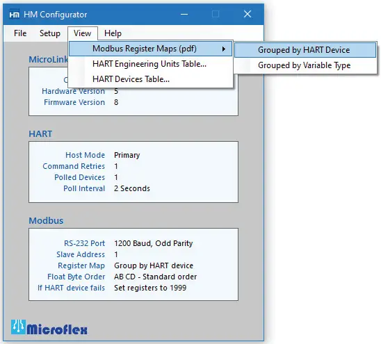 Figure 7. Menu for viewing Modbus register maps.
Setup Registers
The InLink-HM configuration can be changed using the setup and configuration software or by writing to Modbus registers using Modbus-RTU commands 6 or 16. Command 6 writes to a single register, and command 16 writes to a range of Modbus registers. The configuration register values are saved in nonvolatile memory and are not lost when InLink-HM power is removed.
| Modbus Register | Description (high byte, low byte) |
| 772 | HART Failed Code Preset Value |
| 773 | HART Mode Settings |
| 774 | Modbus ဆက်တင်များ |
| 775 | Modbus Port Settings |
| 776 | Hardware Rev, Software Rev |
| 777 | Polled device status |
HART Settings

| Bits 9, 8 HART failed mode. | 0 = Hold last value after HART retries 1 = Preset to register 772 value after HART retries 2 = Preset to IEEE-754 NaN (0 for integers) |
| Bits 7, 6 HART poll retries. | Sets the number of HART device poll retries from 1 to 3. After poll retries, the HART failed mode value is stored in the variable register. |
| Bits 3 – 0 Number of polled devices – 1 | Range is 0 to 15. 0 = 1 polled device. 15 = 16 polled devices. |
မုဒ် ဆက်တင်များ

| Bit 9 – Floating point value byte order | 0 = Standard byte order (AB – CD) 1 = Swapped words (CD – AB) |
| Bit 8 – Modbus device map | 0 = Map register data by HART device 1 = Map register data by variable type |
Serial Port ဆက်တင်များ
Bits 13, 12
00 = တန်းတူညီမျှမှု မရှိပါ။
01 = တောင်
10 = အထူးအဆန်း
Bits 11 – 8
| 1 = 1200 Baud ၁ = ၁ ၁ = ၁ |
၁ = ၁ ၁ = ၁ ၁ = ၁ |
၁ = ၁ ၁ = ၁ ၁ = ၁ |

Polled HART Devices Long Address Table
Device ID information is read from each polled device using the device’s polling address and HART command 0. The reply to command 0 for each polled device is used to populate the long address table. When InLink-HM needs to poll for the device variables, using HART command 3, this table holds the information needed to build the 5-byte long address. Table values can be read using Modbus-RTU command 3. Only the polled device you have configured will contain valid information. The table is updated after each valid device poll.
| ဟတ် ကိရိယာ |
Modbus မှတ်ပုံတင်ပါ။ |
Description (high byte, low byte) |
| 1 | 700 | Preambles, Man. Code or Type |
| 701 | Device Type, ID 1 | |
| 702 | ID 2, ID3 | |
| 2 | 703 | Preambles, Man. Code or Type |
| 704 | Device Type, ID 1 | |
| 705 | ID 2, ID3 | |
| 3 | 706 | Preambles, Man. Code or Type |
| 707 | Device Type, ID 1 | |
| 708 | ID 2, ID3 | |
| 4 | 709 | Preambles, Man. Code or Type |
| 710 | Device Type, ID 1 | |
| 711 | ID 2, ID3 | |
| 5 | 712 | Preambles, Man. Code or Type |
| 713 | Device Type, ID 1 | |
| 714 | ID 2, ID3 | |
| 6 | 715 | Preambles, Man. Code or Type |
| 716 | Device Type, ID 1 | |
| 717 | ID 2, ID3 | |
| 7 | 718 | Preambles, Man. Code or Type |
| 719 | Device Type, ID 1 | |
| 720 | ID 2, ID3 | |
| 8 | 721 | Preambles, Man. Code or Type |
| 722 | Device Type, ID 1 | |
| 723 | ID 2, ID3 | |
| 9 | 724 | Preambles, Man. Code or Type |
| 725 | Device Type, ID 1 | |
| 726 | ID 2, ID3 | |
| 10 | 727 | Preambles, Man. Code or Type |
| 728 | Device Type, ID 1 | |
| 729 | ID 2, ID3 | |
| 11 | 730 | Preambles, Man. Code or Type |
| 731 | Device Type, ID 1 | |
| 732 | ID 2, ID3 | |
| 12 | 733 | Preambles, Man. Code or Type |
| 734 | Device Type, ID 1 | |
| 735 | ID 2, ID3 | |
| 13 | 736 | Preambles, Man. Code or Type |
| 737 | Device Type, ID 1 | |
| 738 | ID 2, ID3 | |
| 14 | 739 | Preambles, Man. Code or Type |
| 740 | Device Type, ID 1 | |
| 741 | ID 2, ID3 | |
| 15 | 742 | Preambles, Man. Code or Type |
| 743 | Device Type, ID 1 | |
| 744 | ID 2, ID3 | |
| 16 | 745 | Preambles, Man. Code or Type |
| 746 | Device Type, ID 1 | |
| 747 | ID 2, ID3 |
HART Device Polling Address Table
The polling address for each polled device is stored in this table. Two polling addresses in each 16-bit register. If address 0 is used, then only one device can be polled, and Device 1 should be set to 0. Address 0 is not valid in multi-drop systems. For HART devices with HART revision 3 through 5, you should use polling addresses 1 – 15. Addresses 16-63 require HART revision 6 or higher.
| Modbus မှတ်ပုံတင်ပါ။ |
HART Device Polling Address (high byte, low byte) |
| 748 | Device 1, Device 2 |
| 749 | Device 3, Device 4 |
| 750 | Device 5, Device 6 |
| 751 | Device 7, Device 8 |
| 752 | Device 9, Device 10 |
| 753 | Device 11, Device 12 |
| 754 | Device 13, Device 14 |
| 755 | Device 15, Device 16 |
Number of Decimal Places Table
When storing the HART variable data in 16-bit Modbus registers, the maximum range is -32768 to 32767. To increase the possible resolution, the variable value read from the HART device is decimal position adjusted before being saved in the 16-bit register. When the register is read, the value must be corrected by the number of decimal places to produce the correct value. The number of decimal places for each variable occupies 4 bits in the register, with one register for each polled device.
| ဒဿမများ | ပြောင်းလဲနိုင်သော အတိုင်းအတာ |
| 0 | -၁၅ မှ ၄၅ |
| 1 | -၁၅ မှ ၄၅ |
| 2 | -၁၅ မှ ၄၅ |
| 3 | -၁၅ မှ ၄၅ |
| 4 | -၁၅ မှ ၄၅ |
| 5 | -၁၅ မှ ၄၅ |
| ဟတ် ကိရိယာ |
Modbus မှတ်ပုံတင်ပါ။ |
ဒဿမနေရာများ အရေအတွက် Description (high byte, low byte) |
| 1 | 756 | PV−SC, TV−FV |
| 2 | 757 | PV−SC, TV−FV |
| 3 | 758 | PV−SC, TV−FV |
| 4 | 759 | PV−SC, TV−FV |
| 5 | 760 | PV−SC, TV−FV |
| 6 | 761 | PV−SC, TV−FV |
| 7 | 762 | PV−SC, TV−FV |
| 8 | 763 | PV−SC, TV−FV |
| 9 | 764 | PV−SC, TV−FV |
| 10 | 765 | PV−SC, TV−FV |
| 11 | 766 | PV−SC, TV−FV |
| 12 | 767 | PV−SC, TV−FV |
| 13 | 768 | PV−SC, TV−FV |
| 14 | 769 | PV−SC, TV−FV |
| 15 | 770 | PV−SC, TV−FV |
| 16 | 771 | PV−SC, TV−FV |
Modbus Register Map – Grouped by HART Device
| မှတ်ပုံတင်ပါ။ | ဖော်ပြချက် |
| 7 | Loop Current Integer |
| ၃၇း၈ | Loop Current Float |
စက် ၁
| မှတ်ပုံတင်ပါ။ | ဖော်ပြချက် |
| 0 | PV Integer |
| 1 | SV Integer |
| 2 | TV Integer |
| 3 | FV Integer |
| 4 | HART အခြေအနေ |
| 5 | MSB = PV UOM, LSB = SV UOM |
| 6 | MSB = TV UOM, LSB = FV UOM |
| ၃၇း၈ | PV Float |
| ၃၇း၈ | SV Float |
| ၃၇း၈ | TV Float |
| ၃၇း၈ | FV Float |
စက် ၁
| 8 | PV Integer |
| 9 | SV Integer |
| 10 | TV Integer |
| 11 | FV Integer |
| 12 | HART အခြေအနေ |
| 13 | MSB = PV UOM, LSB = SV UOM |
| 14 | MSB = TV UOM, LSB = FV UOM |
| ၃၇း၈ | PV Float |
| ၃၇း၈ | SV Float |
| ၃၇း၈ | TV Float |
| ၃၇း၈ | FV Float |
စက် ၁
| 16 | PV Integer |
| 17 | SV Integer |
| 18 | TV Integer |
| 19 | FV Integer |
| 20 | HART အခြေအနေ |
| 21 | MSB = PV UOM, LSB = SV UOM |
| 22 | MSB = TV UOM, LSB = FV UOM |
| ၃၇း၈ | PV Float |
| ၃၇း၈ | SV Float |
| ၃၇း၈ | TV Float |
| ၃၇း၈ | FV Float |
စက် ၁
| မှတ်ပုံတင်ပါ။ | ဖော်ပြချက် |
| 24 | PV Integer |
| 25 | SV Integer |
| 26 | TV Integer |
| 27 | FV Integer |
| 28 | HART အခြေအနေ |
| 29 | MSB = PV UOM, LSB = SV UOM |
| 30 | MSB = TV UOM, LSB = FV UOM |
| ၃၇း၈ | PV Float |
| ၃၇း၈ | SV Float |
| ၃၇း၈ | TV Float |
| ၃၇း၈ | FV Float |
ကိရိယာ 5
| 32 | PV Integer |
| 33 | SV Integer |
| 34 | TV Integer |
| 35 | FV Integer |
| 36 | HART အခြေအနေ |
| 37 | MSB = PV UOM, LSB = SV UOM |
| 38 | MSB = TV UOM, LSB = FV UOM |
| ၃၇း၈ | PV Float |
| ၃၇း၈ | SV Float |
| ၃၇း၈ | TV Float |
| ၃၇း၈ | FV Float |
ကိရိယာ 6
| 40 | PV Integer |
| 41 | SV Integer |
| 42 | TV Integer |
| 43 | FV Integer |
| 44 | HART အခြေအနေ |
| 45 | MSB = PV UOM, LSB = SV UOM |
| 46 | MSB = TV UOM, LSB = FV UOM |
| ၃၇း၈ | PV Float |
| ၃၇း၈ | SV Float |
| ၃၇း၈ | TV Float |
| ၃၇း၈ | FV Float |
စက် ၁
| မှတ်ပုံတင်ပါ။ | ဖော်ပြချက် |
| 48 | PV Integer |
| 49 | SV Integer |
| 50 | TV Integer |
| 51 | FV Integer |
| 52 | HART အခြေအနေ |
| 53 | MSB = PV UOM, LSB = SV UOM |
| 54 | MSB = TV UOM, LSB = FV UOM |
| ၃၇း၈ | PV Float |
| ၃၇း၈ | SV Float |
| ၃၇း၈ | TV Float |
| ၃၇း၈ | FV Float |
စက် ၁
| 56 | PV Integer |
| 57 | SV Integer |
| 58 | TV Integer |
| 59 | FV Integer |
| 60 | HART အခြေအနေ |
| 61 | MSB = PV UOM, LSB = SV UOM |
| 62 | MSB = TV UOM, LSB = FV UOM |
| ၃၇း၈ | PV Float |
| ၃၇း၈ | SV Float |
| ၃၇း၈ | TV Float |
| ၃၇း၈ | FV Float |
စက် ၁
| 64 | PV Integer |
| 65 | SV Integer |
| 66 | TV Integer |
| 67 | FV Integer |
| 68 | HART အခြေအနေ |
| 69 | MSB = PV UOM, LSB = SV UOM |
| 70 | MSB = TV UOM, LSB = FV UOM |
| ၃၇း၈ | PV Float |
| ၃၇း၈ | SV Float |
| ၃၇း၈ | TV Float |
| ၃၇း၈ | FV Float |
ကိရိယာ 10
| မှတ်ပုံတင်ပါ။ | ဖော်ပြချက် |
| 72 | PV Integer |
| 73 | SV Integer |
| 74 | TV Integer |
| 75 | FV Integer |
| 76 | HART အခြေအနေ |
| 77 | MSB = PV UOM, LSB = SV UOM |
| 78 | MSB = TV UOM, LSB = FV UOM |
| ၃၇း၈ | PV Float |
| ၃၇း၈ | SV Float |
| ၃၇း၈ | TV Float |
| ၃၇း၈ | FV Float |
Devicer 11
| 80 | PV Integer |
| 81 | SV Integer |
| 82 | TV Integer |
| 83 | FV Integer |
| 84 | HART အခြေအနေ |
| 85 | MSB = PV UOM, LSB = SV UOM |
| 86 | MSB = TV UOM, LSB = FV UOM |
| ၃၇း၈ | PV Float |
| ၃၇း၈ | SV Float |
| ၃၇း၈ | TV Float |
| ၃၇း၈ | FV Float |
ကိရိယာ 12
| 88 | PV Integer |
| 89 | SV Integer |
| 90 | TV Integer |
| 91 | FV Integer |
| 92 | HART အခြေအနေ |
| 93 | MSB = PV UOM, LSB = SV UOM |
| 94 | MSB = TV UOM, LSB = FV UOM |
| ၃၇း၈ | PV Float |
| ၃၇း၈ | SV Float |
| ၃၇း၈ | TV Float |
| ၃၇း၈ | FV Float |
စက် ၁
| မှတ်ပုံတင်ပါ။ | ဖော်ပြချက် |
| 96 | PV Integer |
| 97 | SV Integer |
| 98 | TV Integer |
| 99 | FV Integer |
| 100 | HART အခြေအနေ |
| 101 | MSB = PV UOM, LSB = SV UOM |
| 102 | MSB = TV UOM, LSB = FV UOM |
| ၃၇း၈ | PV Float |
| ၃၇း၈ | SV Float |
| ၃၇း၈ | TV Float |
| ၃၇း၈ | FV Float |
စက် ၁
| 104 | PV Integer |
| 105 | SV Integer |
| 106 | TV Integer |
| 107 | FV Integer |
| 108 | HART အခြေအနေ |
| 109 | MSB = PV UOM, LSB = SV UOM |
| 110 | MSB = TV UOM, LSB = FV UOM |
| ၃၇း၈ | PV Float |
| ၃၇း၈ | SV Float |
| ၃၇း၈ | TV Float |
| ၃၇း၈ | FV Float |
စက် ၁
| မှတ်ပုံတင်ပါ။ | ဖော်ပြချက် |
| 112 | PV Integer |
| 113 | SV Integer |
| 114 | TV Integer |
| 115 | FV Integer |
| 116 | HART အခြေအနေ |
| 117 | MSB = PV UOM, LSB = SV UOM |
| 118 | MSB = TV UOM, LSB = FV UOM |
| ၃၇း၈ | PV Float |
| ၃၇း၈ | SV Float |
| ၃၇း၈ | TV Float |
| ၃၇း၈ | FV Float |
စက် ၁
| 120 | PV Integer |
| 121 | SV Integer |
| 122 | TV Integer |
| 123 | FV Integer |
| 124 | HART အခြေအနေ |
| 125 | MSB = PV UOM, LSB = SV UOM |
| 126 | MSB = TV UOM, LSB = FV UOM |
| ၃၇း၈ | PV Float |
| ၃၇း၈ | SV Float |
| ၃၇း၈ | TV Float |
| ၃၇း၈ | FV Float |
Modbus Register Map – Grouped by Variable Type
ဗျာ ၂.၁
| Loop Current − Integer | 112 |
| Loop Current − Float | ၃၇း၈ |
| 16−bit Signed Registers | 16−bit Unsigned | |||||||
| ဟတ် ကိရိယာ |
PV ကိန်းပြည့် |
SV ကိန်းပြည့် |
TV ကိန်းပြည့် |
FV ကိန်းပြည့် |
ဟတ် အဆင့်အတန်း |
UOM PV, SV |
UOM TV, FV |
|
| 1 | 0 | 16 | 32 | 48 | 64 | 80 | 96 | |
| 2 | 1 | 17 | 33 | 49 | 65 | 81 | 97 | |
| 3 | 2 | 18 | 34 | 50 | 66 | 82 | 98 | |
| 4 | 3 | 19 | 35 | 51 | 67 | 83 | 99 | |
| 5 | 4 | 20 | 36 | 52 | 68 | 84 | 100 | |
| 6 | 5 | 21 | 37 | 53 | 69 | 85 | 101 | |
| 7 | 6 | 22 | 38 | 54 | 70 | 86 | 102 | |
| 8 | 7 | 23 | 39 | 55 | 71 | 87 | 103 | |
| 9 | 8 | 24 | 40 | 56 | 72 | 88 | 104 | |
| 10 | 9 | 25 | 41 | 57 | 73 | 89 | 105 | |
| 11 | 10 | 26 | 42 | 58 | 74 | 90 | 106 | |
| 12 | 11 | 27 | 43 | 59 | 75 | 91 | 107 | |
| 13 | 12 | 28 | 44 | 60 | 76 | 92 | 108 | |
| 14 | 13 | 29 | 45 | 61 | 77 | 93 | 109 | |
| 15 | 14 | 30 | 46 | 62 | 78 | 94 | 110 | |
| 16 | 15 | 31 | 47 | 63 | 79 | 95 | 111 | |
| 32−bit Float Registers | ||||
| ဟတ် ကိရိယာ |
PV မျှောပါ။ |
SV မျှောပါ။ |
TV မျှောပါ။ |
YV မျှောပါ။ |
| 1 | ၃၇း၈ | ၃၇း၈ | ၃၇း၈ | ၃၇း၈ |
| 2 | ၃၇း၈ | ၃၇း၈ | ၃၇း၈ | ၃၇း၈ |
| 3 | ၃၇း၈ | ၃၇း၈ | ၃၇း၈ | ၃၇း၈ |
| 4 | ၃၇း၈ | ၃၇း၈ | ၃၇း၈ | ၃၇း၈ |
| 5 | ၃၇း၈ | ၃၇း၈ | ၃၇း၈ | ၃၇း၈ |
| 6 | ၃၇း၈ | ၃၇း၈ | ၃၇း၈ | ၃၇း၈ |
| 7 | ၃၇း၈ | ၃၇း၈ | ၃၇း၈ | ၃၇း၈ |
| 8 | ၃၇း၈ | ၃၇း၈ | ၃၇း၈ | ၃၇း၈ |
| 9 | ၃၇း၈ | ၃၇း၈ | ၃၇း၈ | ၃၇း၈ |
| 10 | ၃၇း၈ | ၃၇း၈ | ၃၇း၈ | ၃၇း၈ |
| 11 | ၃၇း၈ | ၃၇း၈ | ၃၇း၈ | ၃၇း၈ |
| 12 | ၃၇း၈ | ၃၇း၈ | ၃၇း၈ | ၃၇း၈ |
| 13 | ၃၇း၈ | ၃၇း၈ | ၃၇း၈ | ၃၇း၈ |
| 14 | ၃၇း၈ | ၃၇း၈ | ၃၇း၈ | ၃၇း၈ |
| 15 | ၃၇း၈ | ၃၇း၈ | ၃၇း၈ | ၃၇း၈ |
| 16 | ၃၇း၈ | ၃၇း၈ | ၃၇း၈ | ၃၇း၈ |
ဘေးကင်းရေး ထည့်သွင်းစဉ်းစားမှုများ
| အပိုင်း 2၊ နှင့် အပိုင်း 15၊ Federal Communications Rules and Regulations ၏ အပိုင်း 003 နှင့် အပိုင်း XNUMX အရ ညီညွတ်မှု၊ နှင့် Industry Canada စံချိန်စံညွှန်းများ၏ ICES-XNUMX။ | |
| ဤစက်ပစ္စည်းသည် FCC စည်းမျဉ်းများ၏ အပိုင်း 15 နှင့် ကိုက်ညီပါသည်။ လုပ်ဆောင်ချက်သည် အောက်ပါအခြေအနေနှစ်ခုတွင် အကျုံးဝင်သည်- (1) ဤစက်ပစ္စည်းသည် အန္တရာယ်ရှိသော အနှောင့်အယှက်ဖြစ်စေမည်မဟုတ်ပါ၊ (2) မလိုလားအပ်သောလည်ပတ်မှုကိုဖြစ်စေနိုင်သော အနှောင့်အယှက်များအပါအဝင် ဤစက်ပစ္စည်းသည် လက်ခံရရှိထားသော မည်သည့်အနှောင့်အယှက်ကိုမဆို လက်ခံရပါမည်။ Microflex မှ ရှင်းရှင်းလင်းလင်း အတည်မပြုသော အပြောင်းအလဲများ သို့မဟုတ် ပြုပြင်မွမ်းမံမှုများသည် ဤစက်ပစ္စည်းကို လည်ပတ်ရန်အတွက် အသုံးပြုသူ၏ အခွင့်အာဏာကို ပျက်ပြယ်သွားစေနိုင်သည်။ | |
| ထုတ်လွှတ်မှု EN55022: 1998 Electrostatic Discharge EN61000-4-2:1995၊ A1:1998၊ A2:2001 Radiated Immunity EN 61000-4-3: 2002 Safety Compliance EN 60950-1:2002 |
|
| ဤစက်ပစ္စည်းသည် အဝလွန်ခြင်းမှ အကာအကွယ်မရှိပါ။tages, which may exist on RS-232 ports of computers, and relies on the protection existing in a host computer. | |
| ဤစက်ပစ္စည်းသည် သင့်လျော်သော converters များမှတစ်ဆင့် ဖုန်းလိုင်းသို့ ချိတ်ဆက်ရန်အတွက် ရည်ရွယ်ခြင်းမဟုတ်ပါ၊ ၎င်းသည် over-vol မှ အကာအကွယ်မရှိသောကြောင့် တယ်လီဖုန်းလိုင်းများနှင့် ချိတ်ဆက်ခြင်းမပြုရပါ။tagဤစာကြောင်းများတွင် ရှိနေနိုင်သည် ။ | |
| အသုံးပြုသူသည် အန္တရာယ်ရှိသော vol ရှိသောနေရာများသို့ဝင်ရောက်ခြင်းမှအော်ပရေတာ၏အကာအကွယ်ကိုသေချာစေရမည်။tages သို့မဟုတ် ၎င်းတို့၏ စက်ပစ္စည်းများတွင် အန္တရာယ်ရှိသော စွမ်းအင်များ။ | |
| အသုံးပြုသူသည် field device ၏ချိတ်ဆက်မှု port နှင့် modem ကို field device တွင်ရှိပြီးသားပင်မ circuit တစ်ခုခုမှအခြေခံလျှပ်ကာဖြင့်အနည်းဆုံးခွဲခြားထားကြောင်းသေချာစေရမည်။ |
ကန့်သတ်အာမခံ
Microflex, LLC သည် ဤယူနစ်အား တင်ပို့သည့်နေ့မှစပြီး တစ်နှစ်တာကာလအတွင်း ပစ္စည်းများနှင့် လက်ရာများတွင် ချို့ယွင်းချက်များကို အာမခံပါသည်။ Microflex, LLC သည် အာမခံကာလအတွင်း ချို့ယွင်းချက်ရှိကြောင်း သက်သေပြနိုင်သော စက်ပစ္စည်းများကို ပြုပြင်ခြင်း သို့မဟုတ် အစားထိုးခြင်းတို့ကို ၎င်း၏ရွေးချယ်မှုဖြင့် ဆောင်ရွက်ပေးမည်ဖြစ်သည်။ ဤအာမခံတွင် အစိတ်အပိုင်းများနှင့် အလုပ်သမားတို့ ပါဝင်သည်။
ပစ္စည်းများကို အာမခံလုပ်ငန်းအတွက် လက်ခံခြင်းမပြုမီ ပစ္စည်း၏အပြင်ဘက်တွင် စက်ရုံမှပြန်လာသော ပစ္စည်းခွင့်ပြုချက် (RMA) နံပါတ်ကို ရှင်းရှင်းလင်းလင်း မှတ်သားထားရပါမည်။
Microflex, LLC, believes that the information in this manual is accurate. In the event that a typographical or technical error exists, Microflex, LLC reserves the right to make changes without prior notice to holders of this edition. The reader should consult Microflex, LLC if any errors are suspected. In no event should Microflex, LLC be liable for any damages arising out of or related to this document or the information contained in it.
ဤနေရာတွင် သတ်မှတ်ထားသည့်အတိုင်း MICROFLEX, LLC မှလွဲ၍ အထူးရည်ရွယ်ချက်တစ်ခုအတွက် အာမခံချက်များ သို့မဟုတ် ရောင်းဝယ်မှု သို့မဟုတ် ကြံ့ခိုင်မှုမပြုလုပ်ပါ။ MICROFLEX ၏ အစိတ်အပိုင်းတွင် မှားယွင်းမှု သို့မဟုတ် ပေါ့ဆမှုကြောင့် ဖြစ်ပေါ်လာသော ပျက်စီးဆုံးရှုံးမှုများကို ပြန်လည်ရယူရန် ဖောက်သည်၏အခွင့်အရေးကို ဖောက်သည်မှ ပေးဆောင်သည့် ပမာဏတွင် ကန့်သတ်ထားရမည်။ MICROFLEX, LLC သည် ဒေတာဆုံးရှုံးမှု၊ အကျိုးအမြတ်များ၊ ထုတ်ကုန်အသုံးပြုမှု သို့မဟုတ် မတော်တဆ သို့မဟုတ် နောက်ဆက်တွဲဖြစ်နိုင်သော ပျက်စီးမှုများကြောင့် ဖြစ်ပေါ်လာသော ပျက်စီးဆုံးရှုံးမှုများအတွက် တာဝန်မကင်းပါ။ Microflex, LLC ၏ တာဝန်ဝတ္တရားကန့်သတ်ချက်သည် ပေါ့ဆမှုအပါအဝင် စာချုပ်တွင်ဖြစ်စေ၊ ညှဉ်းပန်းနှိပ်စက်မှုဖြစ်စေ ၊ ပေါ့ဆမှု အပါအဝင် အရေးယူမှုပုံစံမည်သို့ပင်ဖြစ်စေ သက်ရောက်မည်ဖြစ်သည်။ Microflex, LLC ကို ဆန့်ကျင်သည့် မည်သည့်အရေးယူမှုမဆို အရေးယူမှုဖြစ်ပေါ်ပြီးနောက် တစ်နှစ်အတွင်း ယူဆောင်လာရပါမည်။ ဤနေရာတွင် ပေးထားသော အာမခံသည် Microflex၊ LLC ၏ တပ်ဆင်မှု၊ လည်ပတ်မှု၊ သို့မဟုတ် ပြုပြင်ထိန်းသိမ်းမှု ညွှန်ကြားချက်များကို ပိုင်ရှင်များ လိုက်နာရန် ပျက်ကွက်ခြင်းကြောင့် ဖြစ်ပေါ်လာသော ပျက်စီးဆုံးရှုံးမှုများ၊ ပိုင်ရှင်များ၏ထုတ်ကုန်ပြုပြင်မွမ်းမံ; ပိုင်ရှင်၏ အလွဲသုံးစားလုပ်မှု၊ အလွဲသုံးစားမှု သို့မဟုတ် ပေါ့ဆစွာ ပြုမူမှုများ၊ နှင့် ဓာတ်အားချို့ယွင်းမှု သို့မဟုတ် ရေလှိုင်းများ၊ မီး၊ ရေကြီးမှု၊ မတော်တဆမှု၊ တတိယအဖွဲ့များ၏ လုပ်ဆောင်ချက်များ၊ သို့မဟုတ် ကျိုးကြောင်းဆီလျော်စွာ ထိန်းချုပ်မှုပြင်ပမှ အခြားဖြစ်ရပ်များ။

| Microfl ex, LLC ၃၅၉၀၀ တော်ဝင်လမ်း ပအိုဝ်းသား၊တက္ကဆက် ၇၇၄၂၃ ယူအက်စ်အေ |
ဖုန်း ၇၃၆-၇၈၄-၆၀၉၄ ဖက်စ် ၇၃၆-၇၈၄-၆၀၉၄ www.microflox.com |

The HART protocol is supported by the FieldComm Group in Aus and Texas, www.fieldcommgroup.org. HART သည် FieldComm Group ၏ မှတ်ပုံတင်ထားသော ကုန်အမှတ်တံဆိပ်တစ်ခုဖြစ်သည်။
![]()
စာရွက်စာတမ်းများ / အရင်းအမြစ်များ
 |
Microflex InLink-HM 101-0014 HART Protocol Modem Module [pdf] ညွှန်ကြားချက်လက်စွဲ 101-0014, 101-0003, 101-0093, InLink-HM 101-0014 HART Protocol Modem Module, InLink-HM 101-0014, HART Protocol Modem Module, Protocol Modem Module, Modem Module |